
This blog post deals with checking the end play on IH hydraulic torque amplifiers with the heavy duty 4 direct drive clutch plates. This is important because the original design 3 disc direct drive TA's had a lot more room on the quill shaft, so end play was not a factor. The 4th disc (on the heavy duty versions) rides on the end of the quill gear, which makes full use of the quill gear. However if there is too much end play, the 4th disc has the potential of falling off the end of the quill gear.
The instructions that follow are not included in any of the original service manuals because at the time they were written, the heavy duty 4 disc TA had not been developed. These instructions are just my way of doing this procedure, which has worked well for me. You may have another way to achieve the same results.
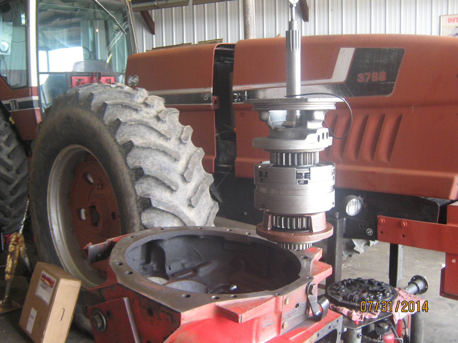
These instructions begin after the center clutch housing has already been removed from the tractor, after the speed transmission and TA assembly have been removed, and you are ready to install the reman heavy duty TA assembly.
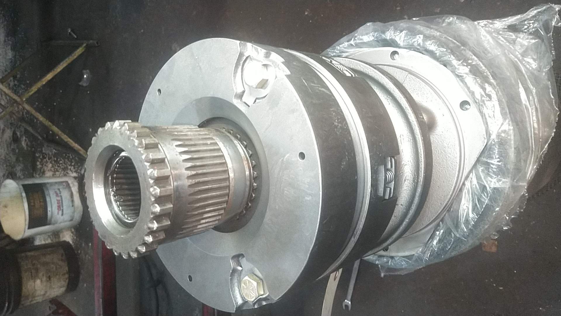
Begin by installing the new bearings in the quill gear/shaft to the correct depths: 9/32" from the large end, and 1 1/32" from the small end. Next, install the new quill in the quill housing. Then position the new TA so that the rear end of the TA is facing up (be sure to leave the hose clamp on the front input shaft). With the rear of the TA facing up...
...use the old quill gear to align the 4 clutch plate splines so the quill slides down into all 4 discs. The quill should rotate smoothly. Make sure all 4 discs appear to be lined up. Work the old quill down into them a few times to make sure it is into the last one.
Then install the new one that is in the quill housing, making sure it is into the 4th disc.
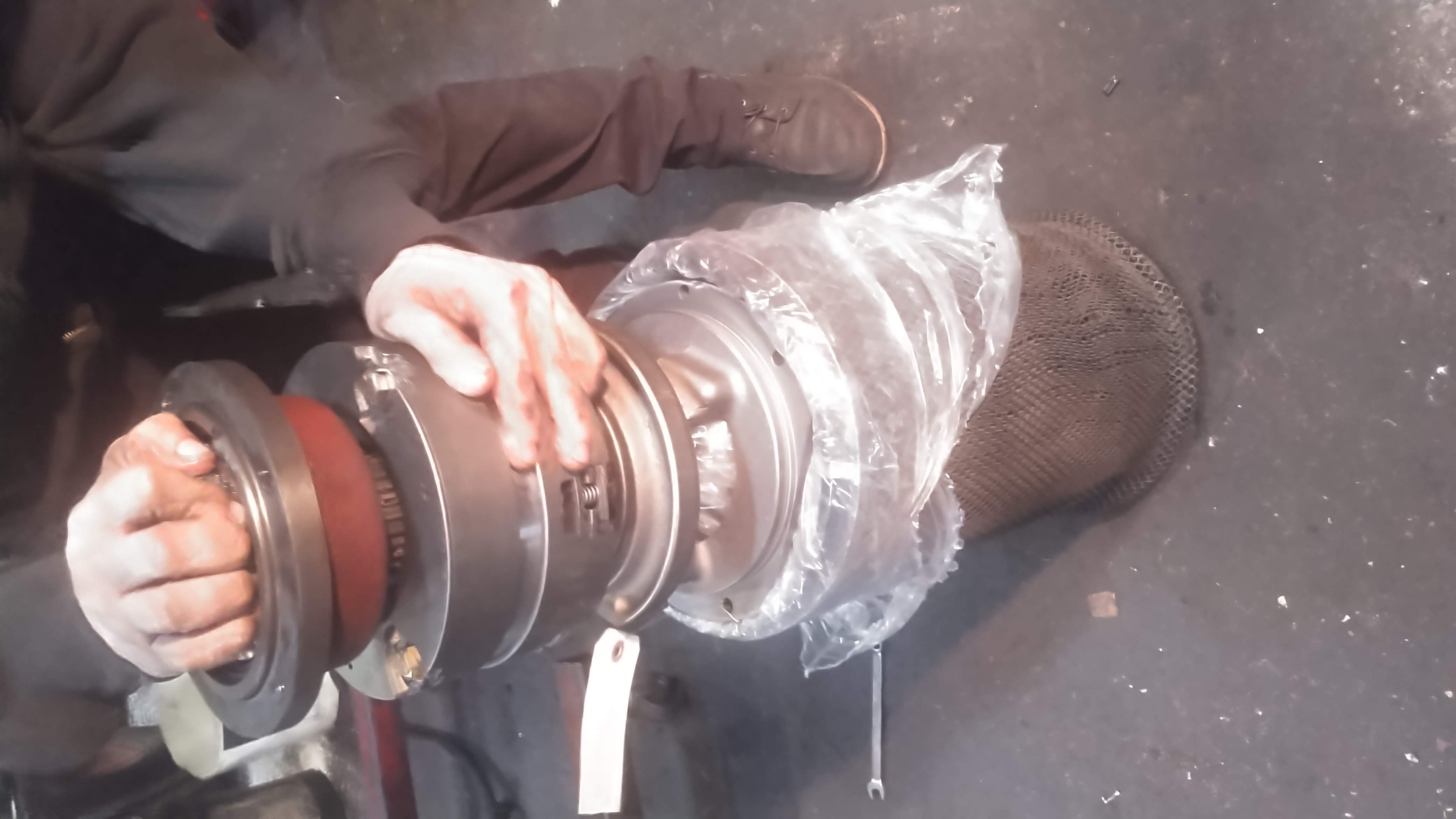
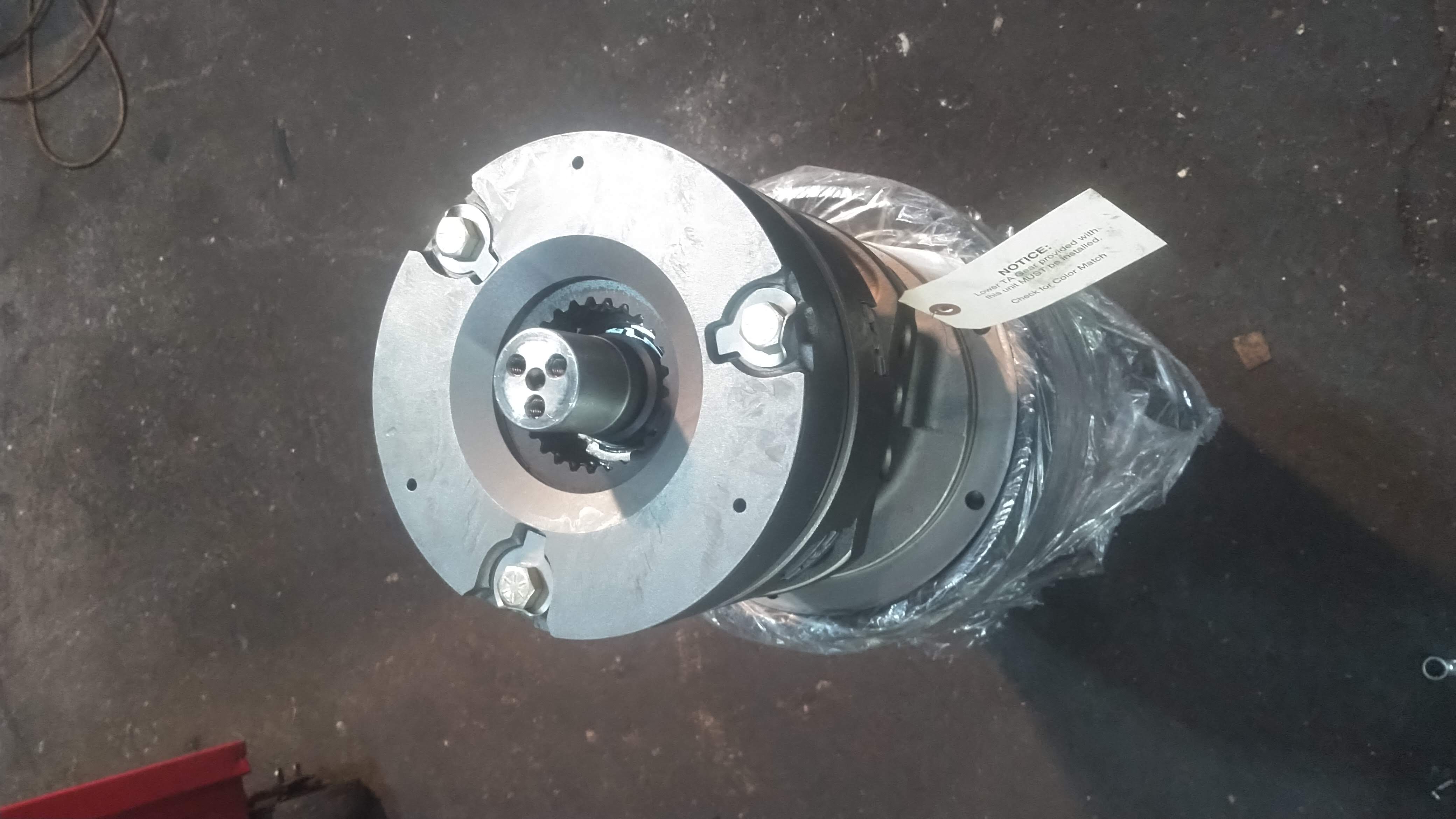
Use a 2 3/4" or 3" x 5/16" coarse thread bolt and a stack of washers to hold the quill and quill housing into the back of the TA. There are 3 holes in the end shaft of the TA; thread the bolt and washers into the shaft into one of the 3 tapped holes so that the quill is held down through all 4 discs.
Prepare the housing; install the 3 jumper tubes into the housing with new o-rings, and pull them out to the inside o-ring, so that they don't interfere with the TA installation. Stand the housing up on the rear surface (bell end or front facing up). Clean the front TA mounting surface and the rear quill housing mounting surface.
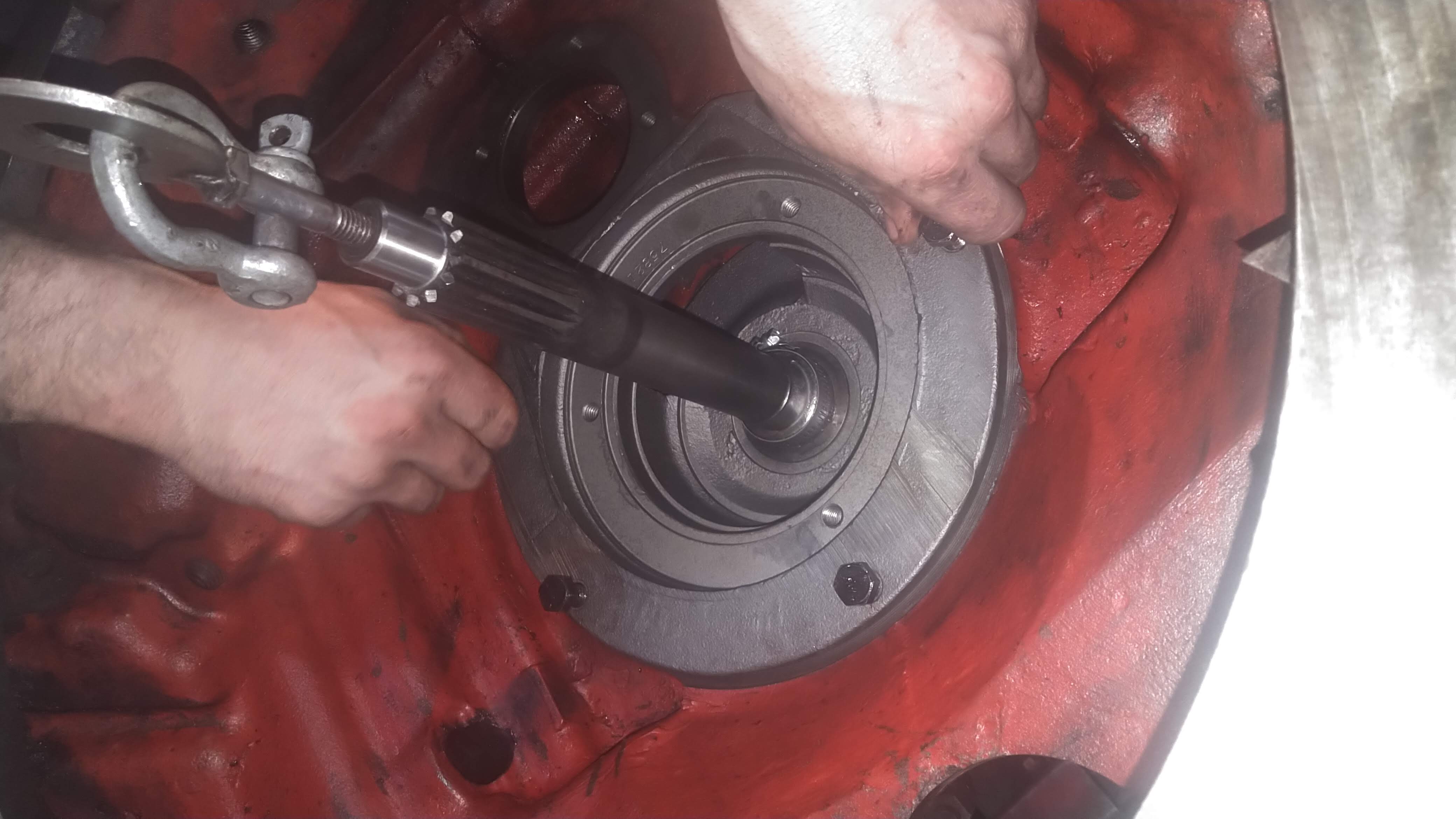
Now attach a 3/8" coarse thread lifting eye bolt into the front input shaft of the TA assembly after it is inverted, so the front shaft is accessible. Then hang the TA assembly (with the quill housing bolted in, and with the 3" bolt and washers) on a hoist with about a 3 foot chain.
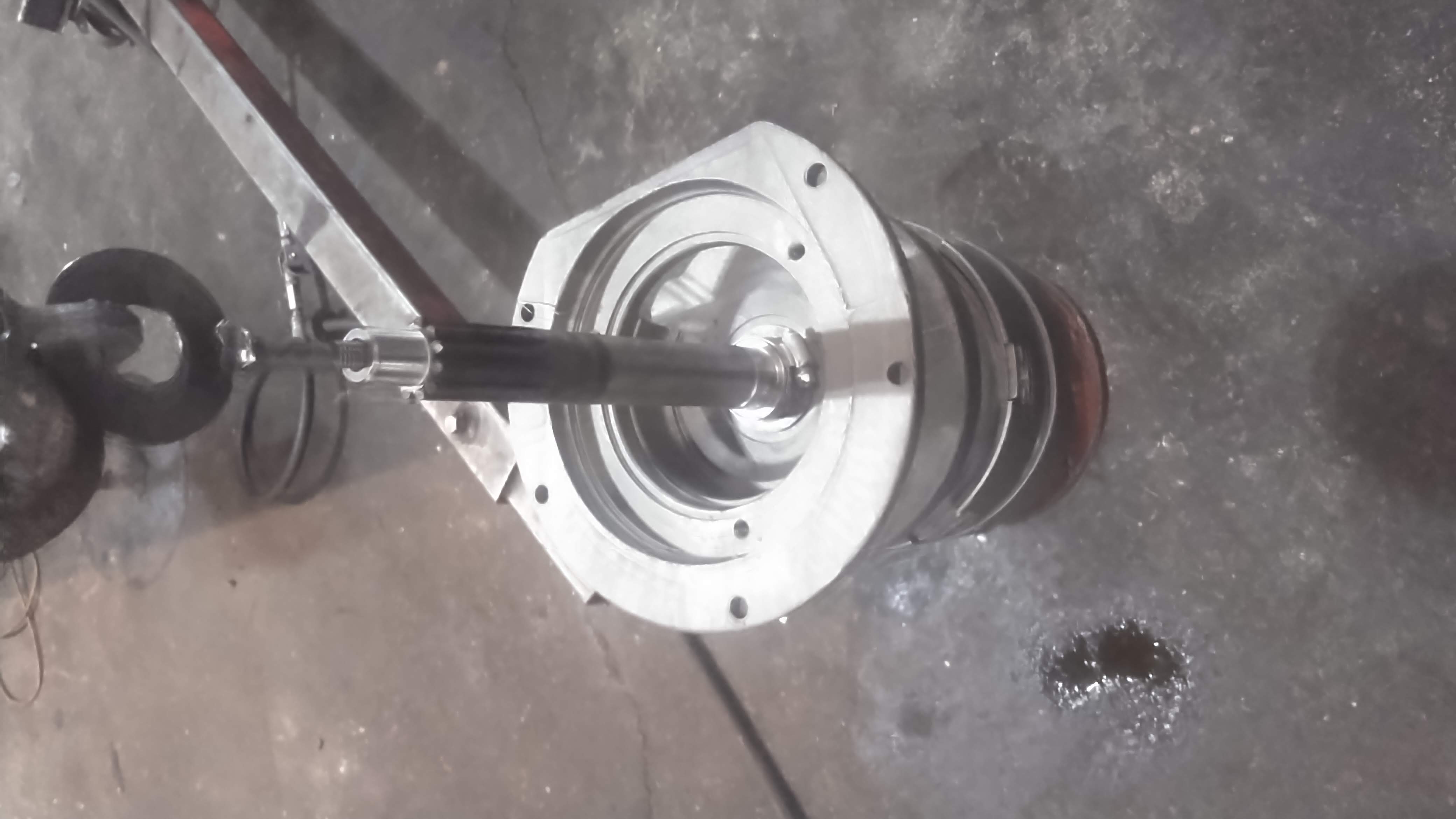
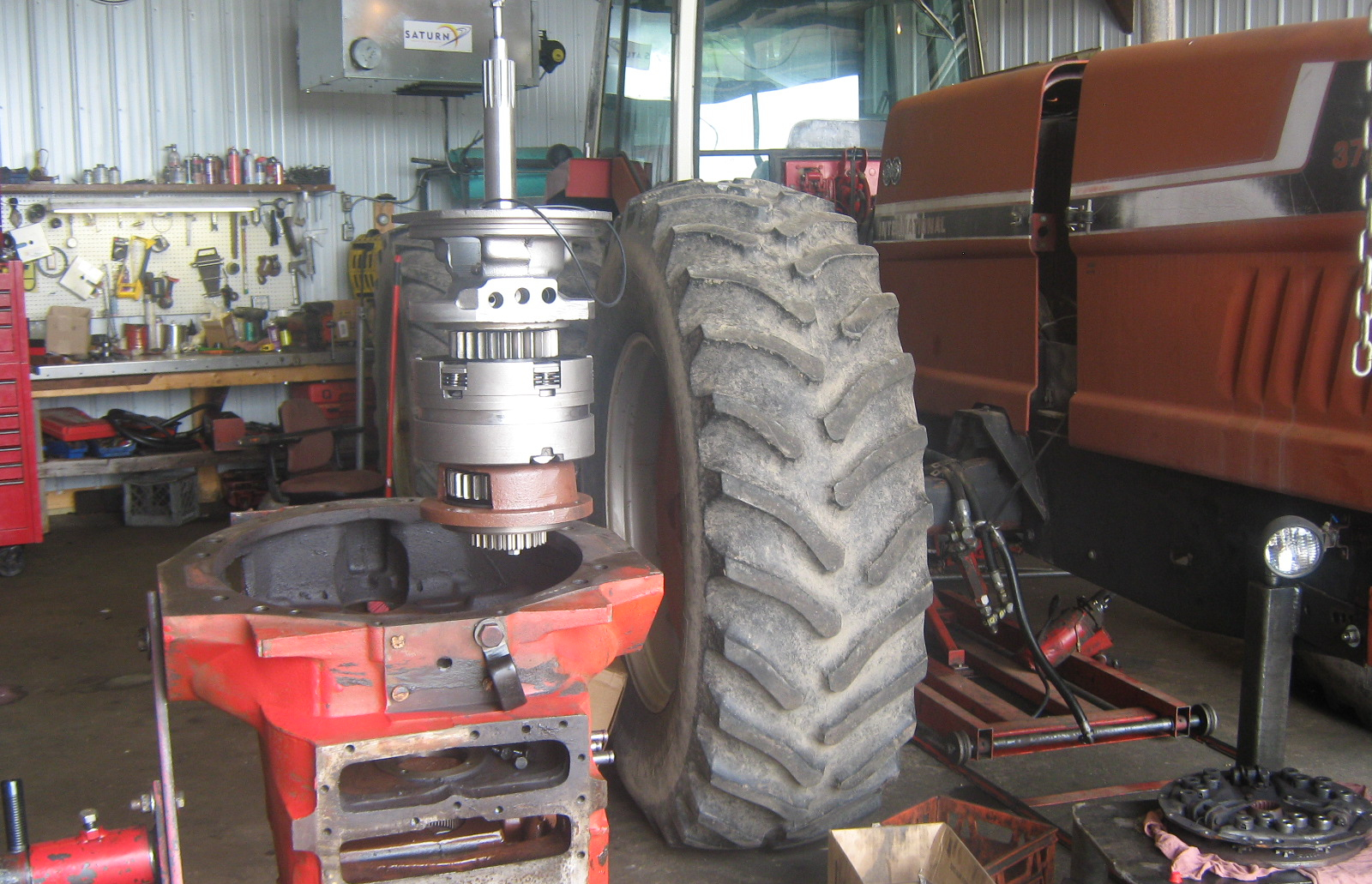
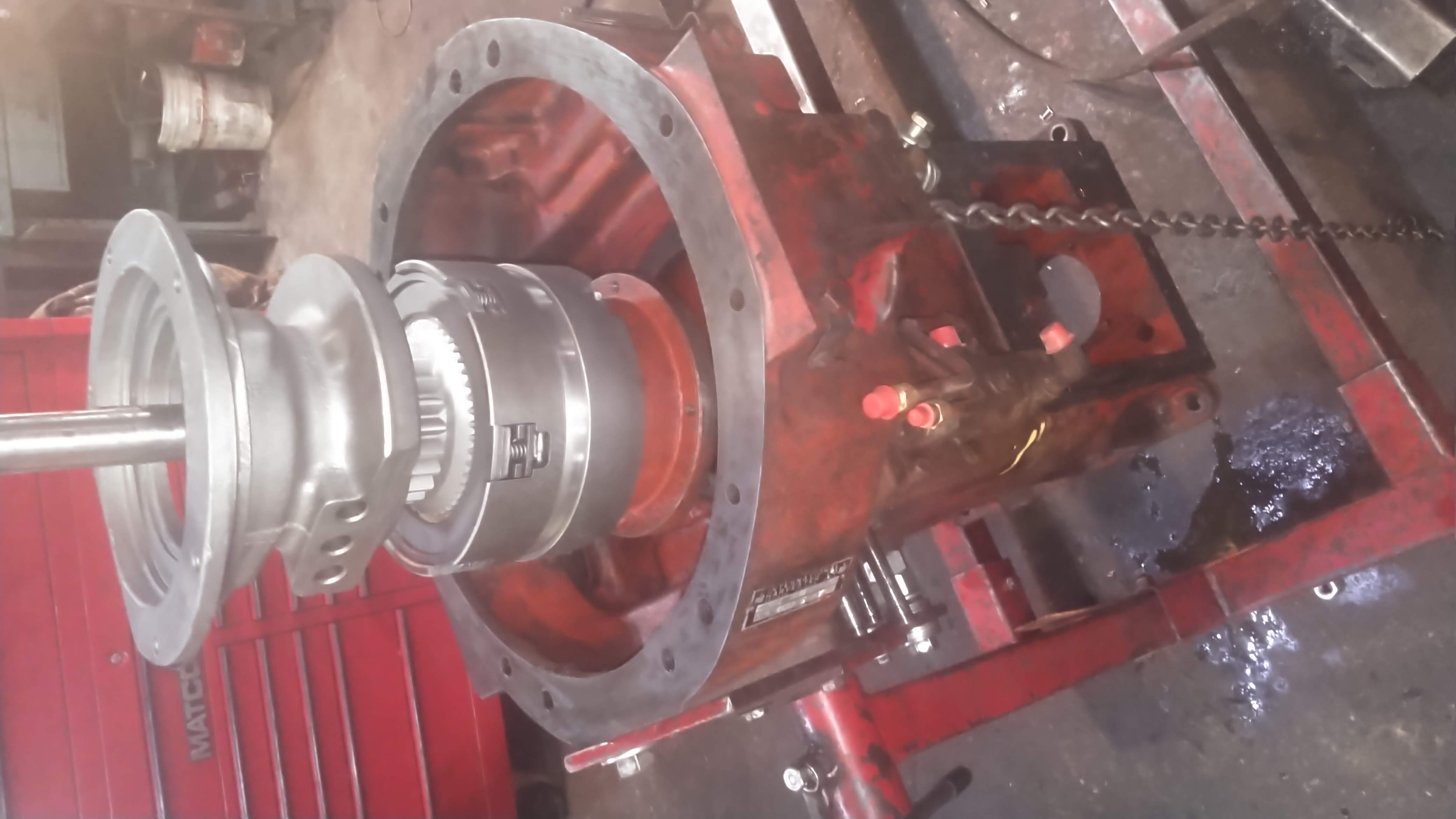
Using the hoist, lower the unit into the housing, pushing or pulling on the chain to align the unit in order to drop it into the housing straight. (Do not install the large o-ring on the front of the assembly at this time). Lower the assembly completely; it should be hanging by the front flange of the TA. Now check to see that the quill housing can rotate freely. If it does not, you need to remove the unit. If it does rotate freely, install the bolts into the front TA flange and tighten them slowly, making sure that the quill housing is still able to rotate freely. If it does rotate freely after the bolts on the front are tight, then you can proceed.
I turn the housing now so that the rear surface is facing up, and the front is facing down. (I have the housing mounted on a engine style stand for easy rotation).
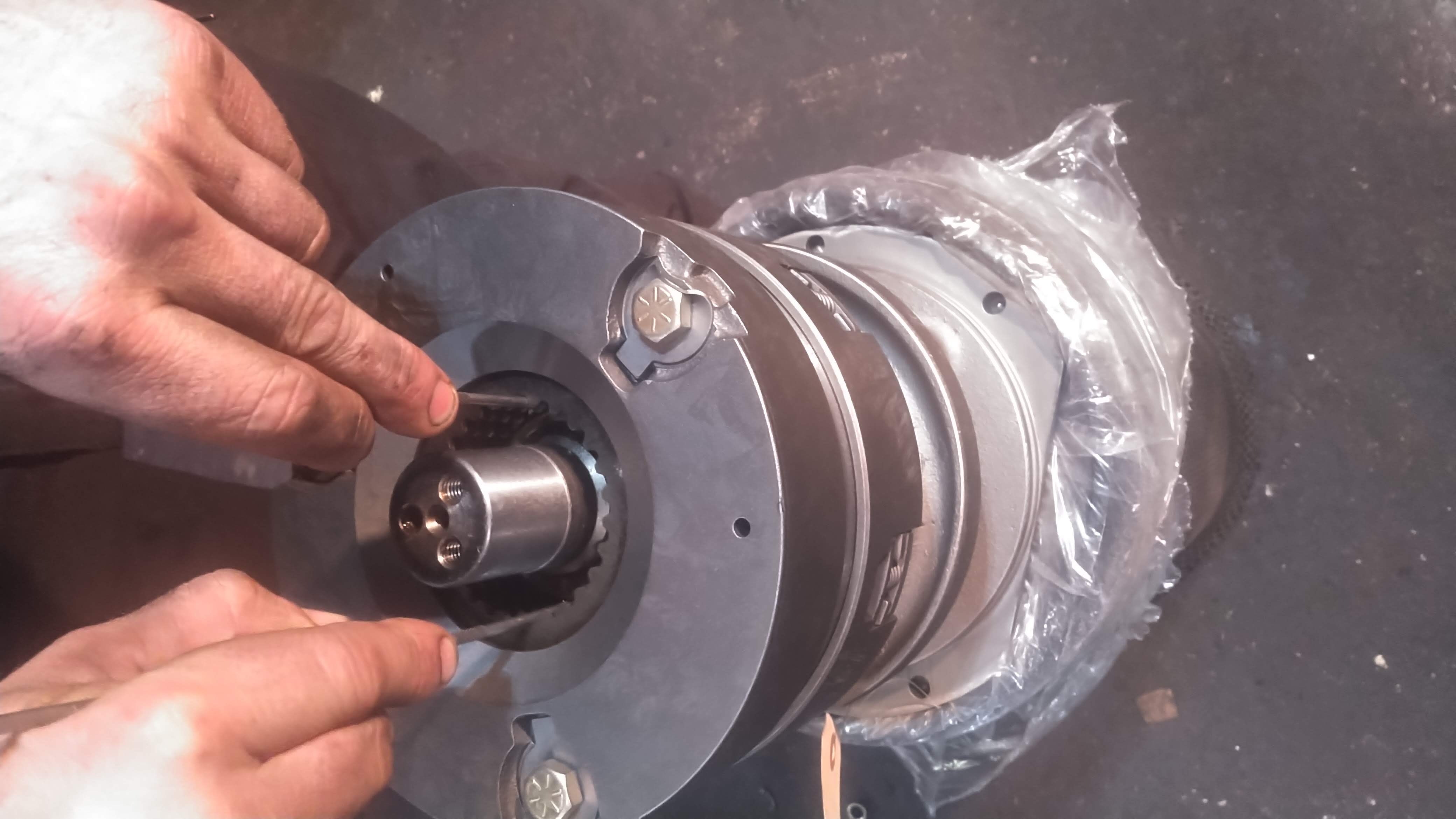
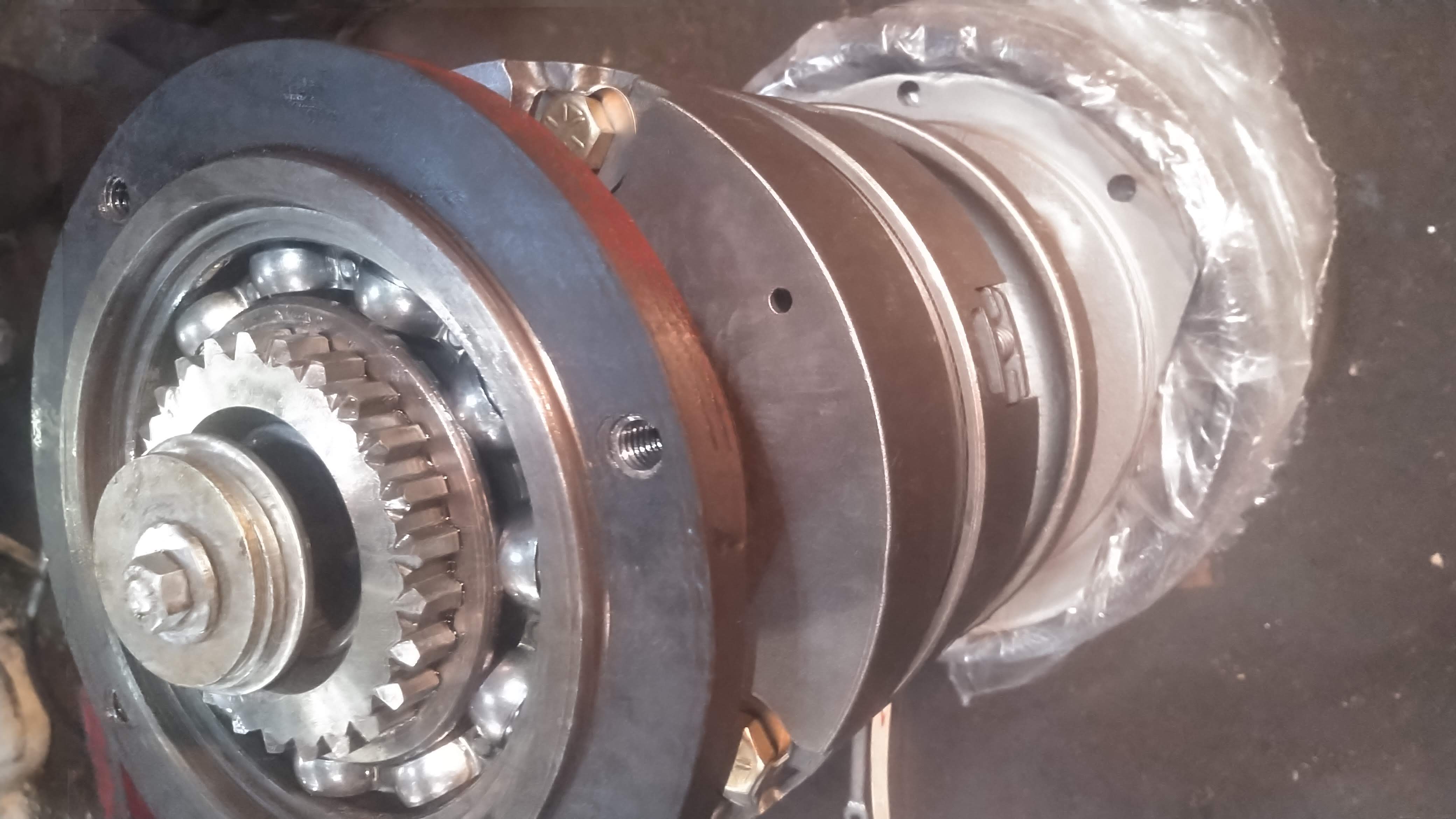
With the rear of the housing facing up, remove the 3" bolt and washers from the quill...
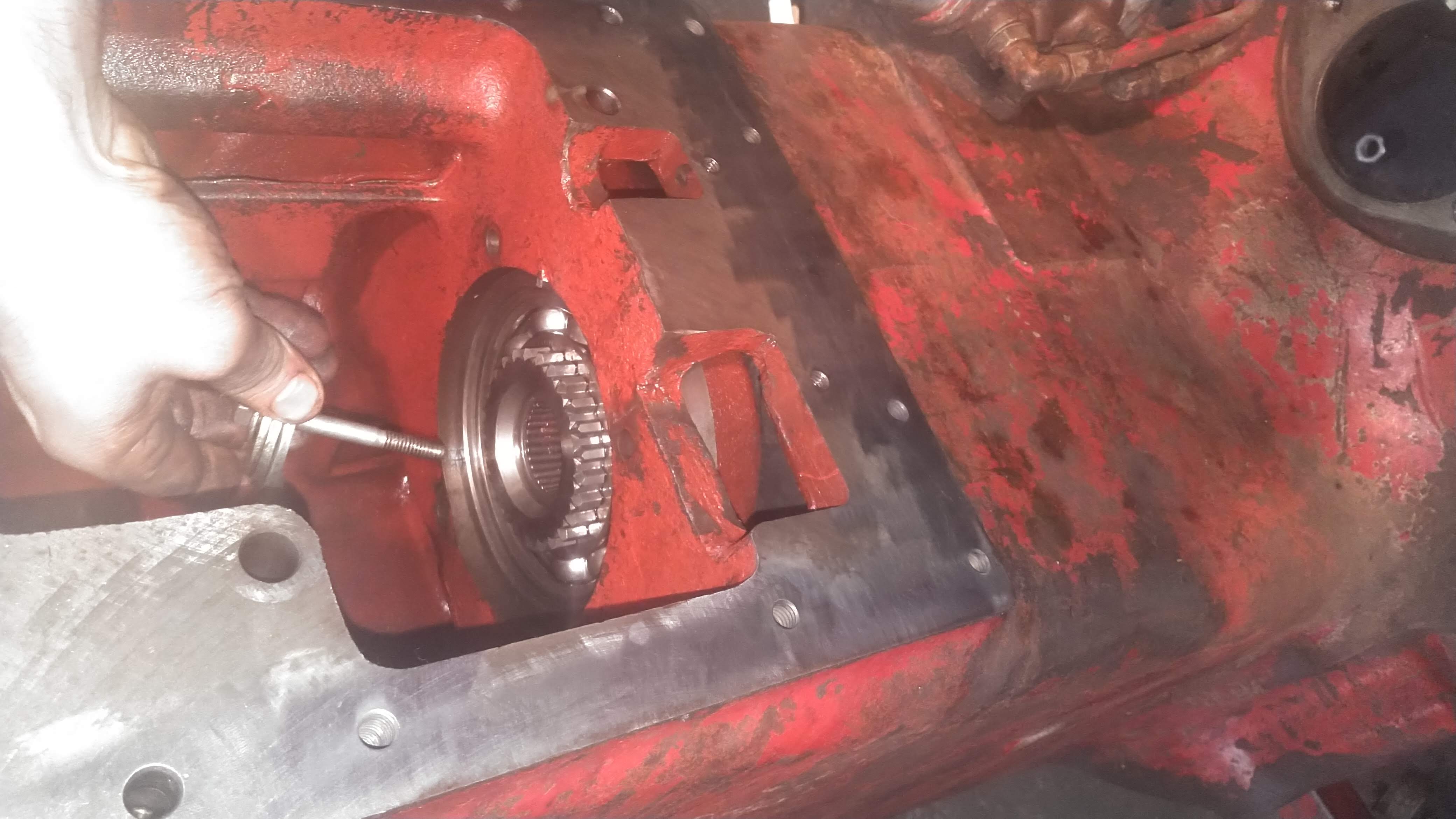
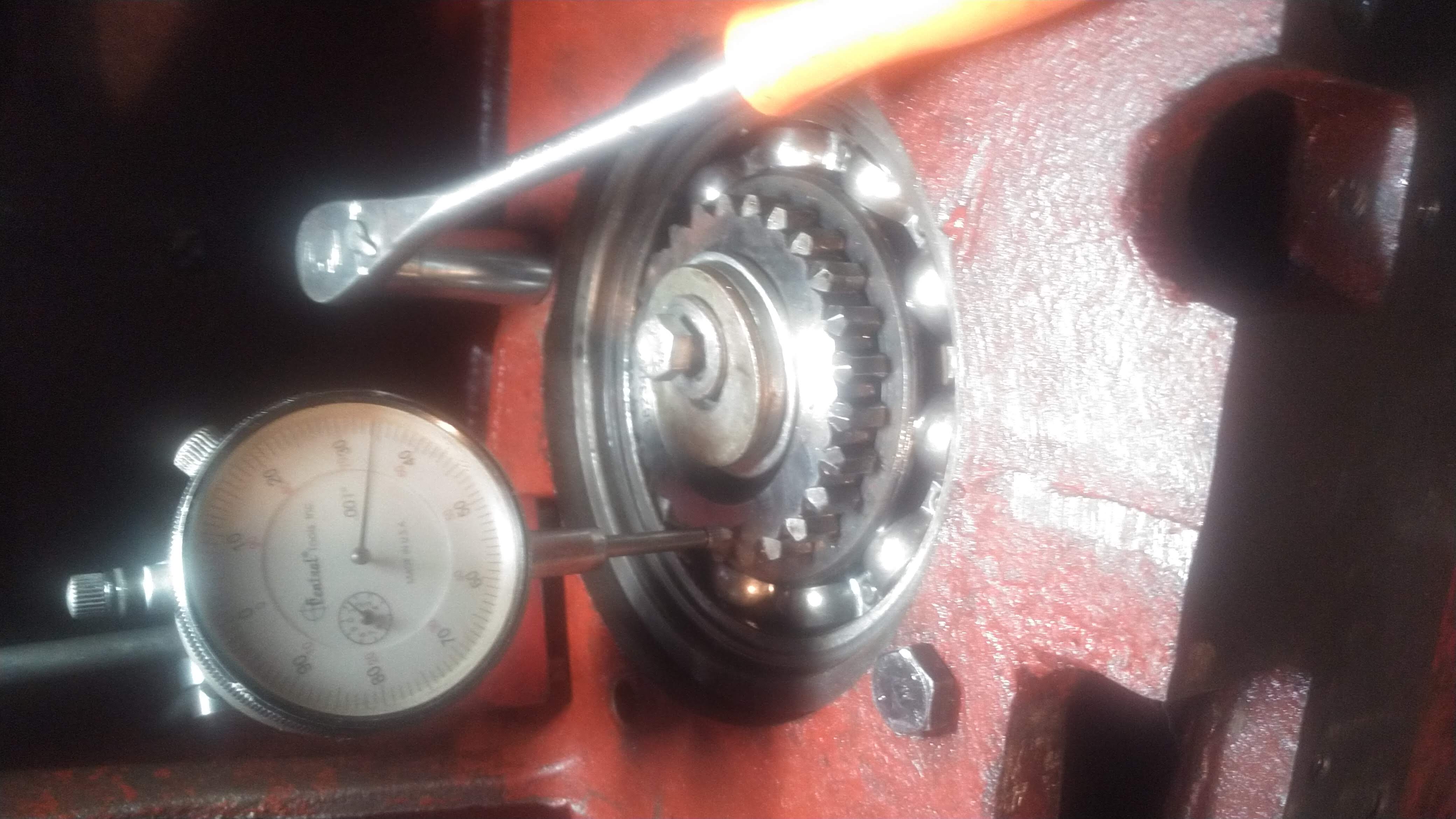
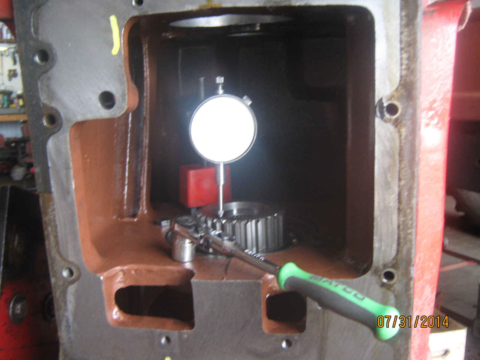
...and thread the 4 bolts into the quill housing, but do not draw them down: just start the threads. Next, set up a dial indicator gauge with the pointer on the rear (or up-facing) large quill gear surface, and zero the dial indicator.
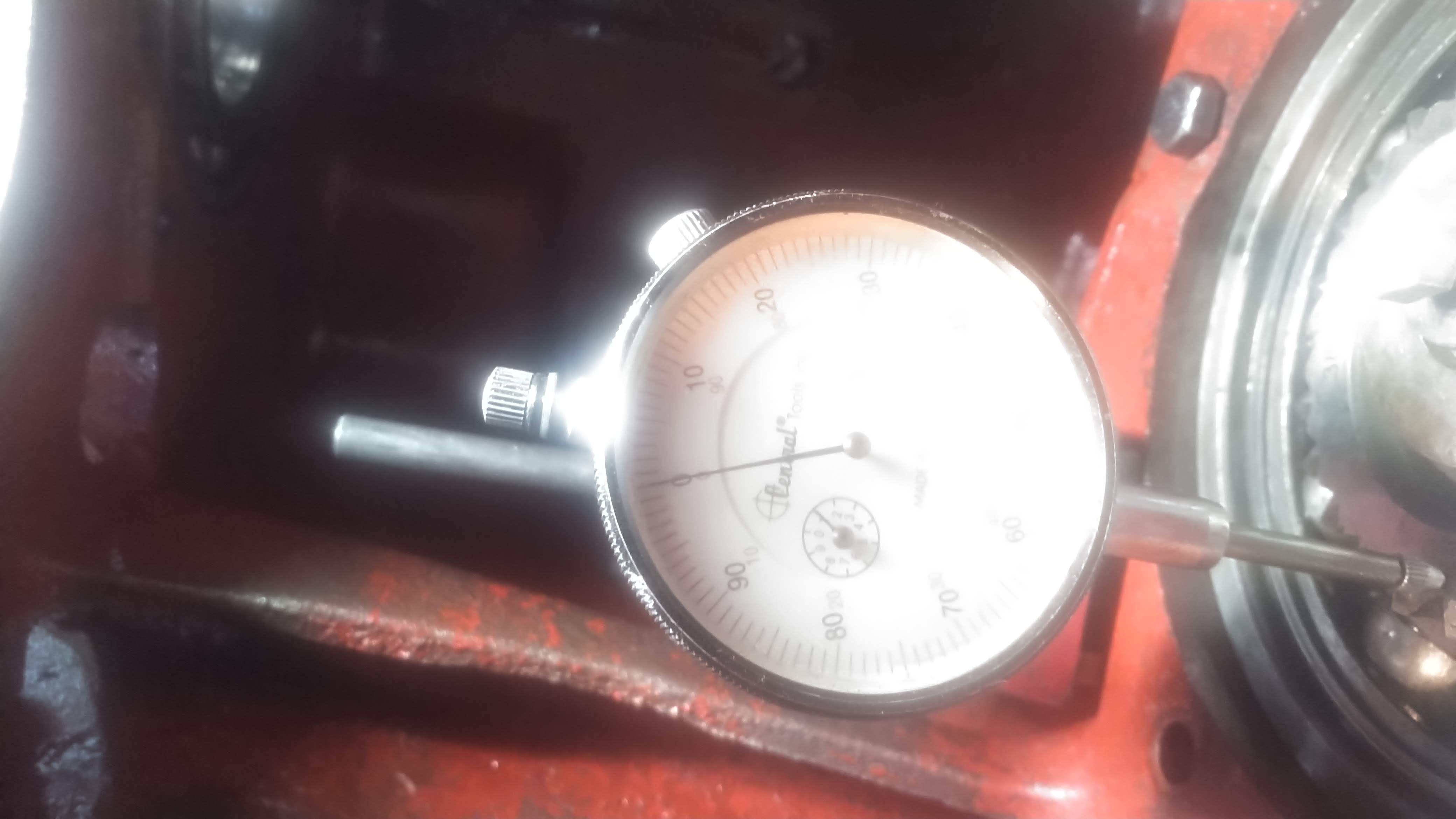
(NOTE: In some of the pictures we may have the 2 1/2 / 3" bolt installed yet but it is loose so as not to interfere with the end play measuring). Now draw the bolts down while watching the dial indicator. With the bolts tight, the dial indicator should read between .005" and .025". This is the correct end play.
If the end play is more than .025", then you will need to install a paper shim to achieve the correct end play (the paper shim is included with the TA assembly). If you have less than .005" of end play, you will need to call me (715-495-4932) and I can explain to you how to correct the problem. Once you determine that the end play is between .005" and .025" you can proceed.
Now remove the 4 bolts, and reinstall the 2"/ 3" bolt with washers, so you can remove the unit to install the large o-ring on the front of the TA. After the unit end play is set correctly, and the large o-ring is installed, and the unit is completely bolted in, you can remove the hose clamp from the front input shaft and proceed with the remaining assembly.
If you encounter any problems or questions call me at (715) 495-4932.
-Joe